The number of options and settings available on a modern ultrasound machine can be quite daunting. That’s why we’ve produced the below guide to help you understand the features available to help you get the best image.
Using Pre-sets
On the control panel or LCD there is a pre-set button. Select from a choice of pre-sets for the appropriate examination. The pre-set will alter the set-up of a range imaging formats, predicting an average scan for your selection. Usually the machine is set so that the probes are switched automatically with the pre-set.
- Abdomen - Usually a `softer’ image with more grey scale therefore enhancing subtle differences in the tissue. Has greater depth of field.
- MSK – a superficial image. Less depth means higher frequency so improved resolution.
- Cardiac - Image with increased contrast (less range of black and white). Has a fast frame rate.
TIPS: If you fiddle with image and feel you have made everything worse, reselect the ‘preset’ and you will be restored to the start image.
Probes
To change a probe there will be a probe selection button. There are sometimes more transducers than ports. If the transducers need to be unplugged, please do this with the probes in freeze mode. Unplugging a live transducer may permanently damage the ultrasound machine.
Basic Controls
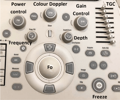
An ultrasound control panel
1. Gain
One of the first controls you will probably have to alter is the gain. This will need constant readjusting throughout the exam. The gain should be altered so the fluid is black and tissue is a comfortable shade of mid grey.
2. TGC
Don’t be afraid to use the TGC scale! The transmitted echoes return to the transducer at different times due to the varied tissue interfaces and depths. The TGC scale is used in order to compensate for the fact that signals returning from deeper reflectors will be weaker than the signals returning from superficial reflectors. This is due to attenuation of the ultrasound wave. If the ultrasound image were formed directly by the raw returned echoes, the image would appear lighter in superficial layers and darker in deep layers but TGC is used to overcome this artefact. Some images are created through a more extreme range. For example, the bladder which has an excellent acoustic transmission and adjacent bowel gas does not.
Tips: Remember to reset the TGC to straight when moving to a different field. A manual TGC will remain in the slope set until reset, even for the next exam/patient.
Tips: The machine may have an ‘Image optimisation’ or ‘Quick scan’ button. It does what it says and can give a predicted image alteration. Worth a try!
- Sometimes called, Auto Optimize, Auto Tunking, or Tissue Equalization.
- Machines often have a way to store favourite setting preferences so each user can default to the alterations they like. Each user can have their own pre-set default and name them.
3. Focal Zone
Shows as a small side face arrow at side of image. This should be moved to be at the level of the area of interest or slightly superficial to it. The beam is focused, i.e. the beam width will become concentrated at this level. This will improve the resolution.
Selecting more than one focal zone creates a broader improvement over the depth of image but produces a slower frame rate. The image may become too ‘swimmy’ to interpret.
4. Frequency Selection
A higher frequency (bigger number in MHz) increases image resolution. However, the penetration or depth of field decreases. Most probes are multi frequency and will display the range of frequencies which can be used. Some probes will give choices of ‘Res’, ‘Gen’ or ‘Pen’.
Tips: Try different settings in each image you take. You’ll want the highest possible frequency setting that allows you to see the anatomy you’re viewing.
5. Tissue Harmonic Imaging
This facility may not be on all probes and perhaps not on older machines.
Tissue harmonics reduces noise artifact. It works by sending one frequency and listening at double the frequency. Harmonic frequencies are reflected back to the transducer. The second harmonic is used and the fundamental frequency is filtered out. For example, a 3MHz pulse listens at 6MHz. The wave difference reduces the side lobe artifact that creates untrue noise. The disadvantage is usually loss of penetration, although manufacturers have compensation methods within the system.
It is worth trying the image with harmonics on and off. It may not help for deep structures due to loss of penetration
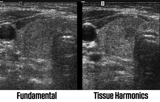
Harmonic imaging
A machine with harmonics will have a ‘THI’, ‘Harm’, ‘HI’, or similar button/control on the machine. An icon will be displayed on the screen if harmonics are selected. If harmonics are used, the frequency display may change from a number range (e.g. MHz) to a word range (e.g. high/pen, low/high).
6. Speckle Reduction Imaging
May be called: SRI, SRI HD, XRes, iClear, Adaptive Speckle Reduction, MView, SCI, SonoHD, ApliPure+, TeraVision or SRF.
It is a computer enhancement of the image that identifies strong and weak signals and exaggerates the difference between them. It enhances the stronger pixels and reduces or removes the weaker. It produces a cleaner image, particularly borders/ boundaries.
It can be used as a post processing facility, selected after the image is frozen. The disadvantage is that it is a computer selected image and is removing ‘true’ echoes.
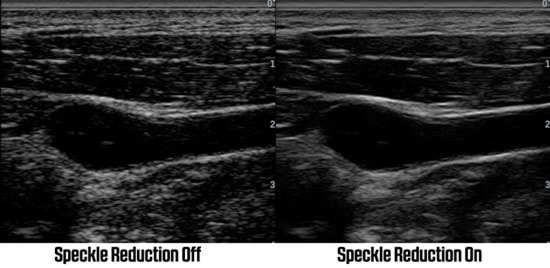
Speckle reduction
7. Compound Imaging
May be called: CrossXBeam, CRI, SonoCT, iBeam, OmniBeam, XView, SonoMB, ApliPure, or Spatial Compounding.
The ultrasound probe sends a pulse in a line and listens. With Compound imaging, the pulse is sent at multiple angles. This helps by imaging structures from different angles, effectively looking at it from different views. This enables untrue image reduction, another way of noise reduction.
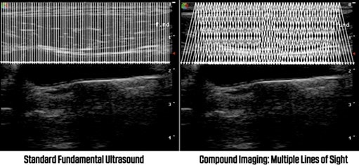
Compound imaging
The image on the left shows the fundamental ultrasound signals perpendicular to the probe. The right shows compound imaging sending and receiving signals from different angles. This is another way to increase image resolution but may compromise with increased frame rate. It is not available on sector transducers and is only suitable for superficial structures.
Advanced optimisation of your ultrasound image
8. Dynamic Range (Compression)
This selects the ‘shade of grey’ range. A higher number of grey shades produces a softer, smoother image but may soften the subtle differences in tissue. Less range of greys gives a harder, more contrast image, ideal for cardiac applications.
9. Ultrasound Grey Maps
Similar to dynamic range but enhances how dark the black is and how bright the white is. This is based upon the strength of the ultrasound signal. Using an ultrasound grey map exaggerates the received image.
10. Line Density
Increasing the line density increases the number of scan lines in the image. This improves the image resolution. However, there is a reduction in frame rate. Usually anything less than 12 frames per second is too slow for comfortable speed.
11. Frame Average/Persistence
Multiple frames of the image are averaged and effectively overlapped with the next frame. This is another computer generated way to reduce noise.
12. Edge Enhancement
Computer generated exaggeration of differences between adjacent signals. If the difference is large it will be enhanced which makes images edges clearer/ more pronounced.
Imaging Optimisation – the pros and cons
Contrast - Adjusts contrast of B Mode image.
- Advantage. Increased contrast = decrease background noise.
- Disadvantage. Decreased dynamic range.
Focus - Focuses ultrasound beam at specified zone.
- Advantage. Increased resolution with multiple zones over the whole image.
- Disadvantage. Decreased frame rate with more focal zones.
Frame Correlation - Interpolation between adjacent frames.
- Advantage. Increased frame correlation = Reduced noise.
- Disadvantage. Increased frame correlation = Causes blurring of movement.
Line Density - Changes the scanning line density, i.e. how close the lines of information are together.
- Advantage. High line density improves lateral resolution.
- Disadvantage. Decreases the frame rate, (images per second).
Acoustic Power - Drive Voltage Amplitude.
- Advantage. Increased power = Increased penetration.
- Disadvantage. Safety issues. Try to keep MI and TI values below 1.
References
Providian [onlinehttps://www.providianmedical.com/
Radiopaedia [onlinehttps://radiopaedia.org/
Vet Times [onlinehttps://www.vettimes.co.uk/abdominal-ultrasound-pt-1-equipment-controls/
WHO physics book